Description
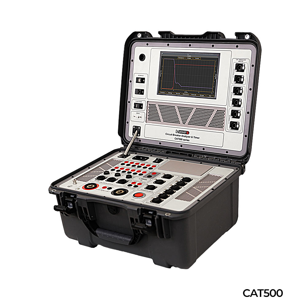
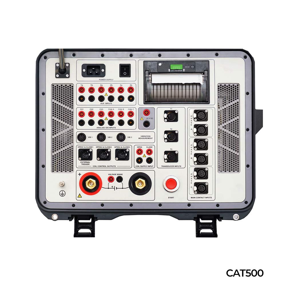
CAT500 summarizes all our experience and knowledge in the design of circuit breaker testing equipment for the past 15 years.
CAT500 introduces some unique testing features and significantly saves the time required for condition assessment of all types of medium- and high voltage circuit breakers.
Features
- Simultaneous timing, static resistance, and dynamic resistance measurement on up to 12 main contacts chambers under BSG conditions by use of CAT modules
- Saves testing time by single cable connection and simultaneous measurement
- Timing, motion, and vibrations measurement
- Minimum trip voltage (MTV) test
- Graphical 10.1” touch-screen color display provides easy control of the test device and results analysis

CAT Modules provide measurement of main arcing contacts timing, static and dynamic resistance of AIS (Air Insulated Substation) circuit breakers with both sides grounded (BSG).

Timing measurements on a GIS breaker with both sides grounded is applicable for the most demanding cases for testing such as single-pole operated GIS CB which has a very low resistance of pole’s enclosures or where CT cannot be included in the measurement circuit between test access points.
Timing measurements on a GIS breaker with both sides grounded is applicable for the most demanding cases for testing such as single-pole operated GIS CB which has a very low resistance of pole’s enclosures or where CT cannot be included in the measurement circuit between test access points.
GIS Test Module consists of three isolated battery-based power sources used for the supplying of each pole of the single-pole controlled CB with a high current.
Test current is in the range of 400-500 A per pole (depending on the battery charge levels and resistance of the tested circuit).
Instead of the measurement of the changes of the current signal at secondary of the CT (when it is outside of grounding switches circuit), changes of the primary injected current will be monitored within the power source.


